

This is a flying Captain America shield that you can make
out of duct tape and cardboard. Make a couple of these and you can battle it
out with your friends Captain America-style!
I had two goals in mind with this project: 1) that the finished shield could be tossed around safely and actually fly stable like a giant Frisbee, and 2) that it could be replicated by almost anyone, independent of their current crafting skills.
For this project I made a couple of different flying shield prototypes. After some experimenting, I eventually reached a design that flew really well . . . and now I'm excited to share it!
I've included a PDF with all the pattern pieces that are required to make this. I worked directly from these finalized pattern pieces to build the finished version of the flying Captain America shield you will see in the following steps and in the video below.
The finished shield is 22.5" in diameter, and weighs 27.5 ounces (780 g). It's hefty, but it flies great. Still, you wouldn't want to knock a little kid in the back of the head with it, but it's certainly a lot safer for throwing around than this version (also made by me).
Here is a video of me throwing my shield roughly a quarter-mile, by my estimate:
And here's a great video of the build process, made by
another youtuber!
I was honored to find this. Check it out:
Step 1: Things You Will Need

Here is what you will need to make your own Flying Captain
America Shield:
- Print-out
of the attached
PDF
- Flat
pieces of cardboard, at least 12" wide across the grain. I used thick
double-ply cardboard.
- Duct
tape, one roll of each: red, white, blue, and regular
- 24"
of webbing or other suitable material for handles
- 74"
of 3/4" polypropylene rope
- Cutting
mat (I have a couple--I got a new double-side Alvin brand
- Utility
knife with extra blades (and/or heavy-duty hobby knife with extra blades)
- Hot
glue gun
- Sharp
scissors
- Marking
pen, like a Sharpie
In each step I will go into more detail about the materials
and tools used.
Step 2: Cut Out Pattern Pieces

Begin by printing out the attached PDF from step one. It
will be easier to use the pattern pieces if you print this on a heavier paper
like card stock.
Carefully cut out each of the pattern pieces using either a sharp blade or scissors. Use tape to join the two sections that form the larger wedge-shaped piece, as shown in the photo.
Carefully cut out each of the pattern pieces using either a sharp blade or scissors. Use tape to join the two sections that form the larger wedge-shaped piece, as shown in the photo.
Step 3: Cut Out Cardboard Wedges

The shield is made up of 20 individual cardboard wedges that
are curled slightly, hot glued together, and then covered with duct tape.

The large wedge-shaped pattern piece labeled "SHIELD" is used to create all the individual sections of cardboard that go together to make the shield.
Trace this pattern piece onto cardboard 20 times, being sure the grain (or lines) of the cardboard run across the narrow width of each wedge-shape.
Use a utility knife with a new, sharp blade to carefully cut out all of these pieces. A sharp blade and cutting mat are a necessity for this step.
Work slowly, be careful, and watch your fingers.
Step 4: Gently Curl Each Shield Piece


For the shield to end up in a slight dome, you will need to
gently curl each wedge-shaped piece.
Use both hands to pull each piece over the sharp edge of a table, which will "break" the stiffness of the cardboard. Your curled pieces should be similar in shape to the ones shown in the first photo.
Use both hands to pull each piece over the sharp edge of a table, which will "break" the stiffness of the cardboard. Your curled pieces should be similar in shape to the ones shown in the first photo.
Step 5: Tack Together Quarter-sections of the Shield


Use hot glue to tack the shield pieces together. You don't
need to use a ton of glue, as you will be adding plenty of tape later on which
will solidify and strengthen the shield.
I recommend beginning by assembling quarter-sections of the shield. This will make it easier to keep things lined up and ensure that the completed shield comes out round. (If you add one piece after the other all the way around the shield, the pieces tend to drift or "creep," and you may not end up exactly where you started.)
Each quarter-section will have five pieces in it. Begin by gluing two pieces together, and then adding the third, fourth and fifth. You don't need to glue the full length of the seam between each two pieces--just the top and bottom couple of inches will do. The most important thing is that the outer edges of the pieces (which will be the outer perimeter of the shield) are lined up evenly.
You will need to gently adjust the curve of each of the pieces so they mate up nicely with each other. There will be small gaps, especially on the top portions of the shield, but this is okay.
Step 6: Join the Quarter-sections


Once you have all four quarter-sections completed, you are
ready to assemble the final dome-shape. You may notice that the four sections
are not quite 90 degrees, as you might have thought they would be. Don't worry,
this is correct and everything will fit together nicely.
Begin by joining two sets of quarter-sections so you have two completed halves.
Now join both halves. This may take an extra set of hands to hold them together while the hot glue cools, since the two halves will naturally want to pull apart. This is where the dome takes it's final shape, as you force these two halves together.
You should now have a "naked" Captain America shield. You're half-way there!
You'll be tempted to take it outside and try to throw it. Don't do it. Resist the urge!
Step 7: Reinforce Backside of Shield

Use strips of regular duct tape to reinforce the seams
between the glued sections on the backside of the shield. Make sure you press
down firmly so the tape sticks well.
Step 8: The Secret to Making It Fly...


A length of suitably heavy rope needs to be added to the
underside perimeter of the shield, which is the trick to making it stable
enough to fly like a Frisbee. It also provides a nice lip for looks, as well as
a place to grip for throwing or catching.
You will need about 74" of 3/4" polypropylene rope, which can be purchased by the foot at most hardware stores.
To keep the rope from fraying when you trim it to length, wrap a few inches of tape around the cut ends. You could use a lighter or torch to fuse the ends as well, but it will all be covered with tape soon enough, so it's probably not worth the effort.
Use hot glue to firmly glue the rope down along the underside edge of the shield.
Step 9: Cover the Edge With Red Duct Tape

Use 6- or 7-inch strips of red duct tape to tape over the
rope and edge of the shield. Try to keep the tape as tight up to the rope as
possible so there aren't any big air pockets along the inside lip of the
shield.
Note that for all pieces of duct tape that you use from here on, you will want to cut them off of the rolls rather than tear them off. This will help keep things clean and neat. This is where a sharp pair of scissors comes in very handy.
Note that for all pieces of duct tape that you use from here on, you will want to cut them off of the rolls rather than tear them off. This will help keep things clean and neat. This is where a sharp pair of scissors comes in very handy.
Step 10: Cover Backside of Shield

Cover the backside of the shield with strips of regular duct
tape.
Try to be as efficient in covering as you can in order to keep the weight down, but make sure every bit of cardboard is covered.
Try to be as efficient in covering as you can in order to keep the weight down, but make sure every bit of cardboard is covered.
Step 11: Attach Handles


You have some options here.
I had some 1 1/2" webbing that I salvaged off of an old gym bag which worked very well as handles for my shield. If you have some 3/4" webbing, that would work equally well. You could also just as easily fashion some handles out of a few layers of duct tape.
Whatever you choose, cut two strips of your material about 12" each (add a little more if you have bulky forearms). Hot glue the ends down, positioning the handles similarly to what is shown in this photo, and reinforce all around with more duct tape.
Step 12: Cover Top of Shield
Cut strips of red duct tape and cover the top of the shield.
Try to keep everything as smooth and wrinkle-free as possible.
Step 13: Add Center Blue Circle

The pattern piece labeled "CENTER CIRCLE" is used
to draw out the shapes that will be used to make the center blue circle on the
shield.
Lay out three 24" strips of blue duct tape, overlapping each piece about 1/4", similar to what is shown in the second photo. (I initially only laid out enough blue tape to draw out 6 pattern pieces, so I had to do this part twice.)
Lay out three 24" strips of blue duct tape, overlapping each piece about 1/4", similar to what is shown in the second photo. (I initially only laid out enough blue tape to draw out 6 pattern pieces, so I had to do this part twice.)

Trace the pattern piece 12 times onto the blue tape, and use a sharp hobby knife or utility knife to cut out the wedge-shapes. When you pull them up off the cutting mat, be sure to pull them up starting with the layer of tape that is on the bottom. This way the separate pieces of tape that make up each wedge will all stay in place.
You should be able to see where the exact center of the shield is, based on where the cardboard wedges meet. If you can't see this through the layers of tape, squish the tape down with your fingers to feel where the center of the shield is. Make a mark or poke a small hole with a pin if you need to, to use as guide to help you place the blue wedge-shapes in the center of the shield.
Step 14: Add White Ring

The white ring is made from white duct tape, and is
completed in similar fashion to the center blue circle.
Trace the pattern piece labeled "WHITE CIRCLE" 8 or 9 times onto two strips of white duct tape, as shown in the second photo.
For placement of the white ring on the shield, I just eyeballed it. The goal is to have three rings of equal width (red, white, red). If it looks funny or crooked, you can always pull it up and re-do it.
A more precise method would be to use a ruler or measuring tape to place a few marks around the shield from the center point to aid in the placement of the white ring. The inside edge of the white ring should be placed about 7 1/8" (181 mm) from the center point of the shield. (Thanks to Iron-Man227 for this tip!)
Step 15: Add Center Star


The center star is completed similar to the method used in
the last two steps, using the pattern piece labeled "STAR" to draw
out the five sections that make up the star.
When the shield is held level on the left arm, the star should be pointing up. Place all the star pieces accordingly.
When the shield is held level on the left arm, the star should be pointing up. Place all the star pieces accordingly.
Step 16: Clean Up the Shield, and You're Done!

A little bit of denatured alcohol on a rag will quickly
clean off any marker lines left over from tracing your pattern pieces, and will
leave your shield looking slick and shiny.
That's it. You're done!
It may take some practice to be able to throw it well--if you have a hard time throwing a Frisbee, you may struggle with this. Practice with a regular Frisbee if you need to, and work your way up to your awesome homemade Captain America shield. Remember to whip your wrist as you release the shield, to give it plenty of spin.
I'd love to see some photos of your finished shield if you make one. Just upload a photo or two and post them with a comment.
Thanks for checking this out.

Would you like to swing from high rise to high rise with your own special web shooters? All things considered, you will likely need to hold off on that idea for an additional 100 years.
In the mean while, we can make this taunt web shooter. It's a wrist mounted loop weapon that can spear and recover objects. The web shooter can reel in objects from more than 12 feet away.
No hardware encounter is required. You won't need to patch a bundle of capacitors to fabricate this system! I have investigated different approaches to fabricate a comparative gadget. I promise you this is the most straightforward technique. Practically every strategy expects you to assemble an intricate circuit with huge amounts of electrical segments. NOT HERE! While that would be an incredible lesson, I need this undertaking to be fun, simple, and (above all) shabby to make.
Fabricate Time: Two Hours
Fabricate Cost: $20 (I as of now had the greater part of the parts. I attempted to utilize things that individuals for the most part as of now have at home.)
You can assemble this system by proceeding with this content or viewing the video guidelines on the following page. I trust that you find either satisfactory.
Cap tip to How To Lou, Laser Gadgets, and Electro BOOM. I couldn't have completed my undertaking without their educational recordings.
**I'm going to boldly intrude on this Constructable. On the off chance that you like this undertaking please vote in favor of it in the Heroes and Villains Contest!**
Stage 1: How It Works
ELECTROMAGNETISM!
By stimulating a little loop, we can dispatch metal protests a few feet away.
Our curl weapon configuration includes a loop and a metal shoot. The metal dash is fixing to a spool of string. The spool of string is associated with an engine. Setting off the curl dispatches the dash noticeable all around. The apparatus engine can recover the dash and whatever the shoot has speared.
Stage 2: Parts List
Principle Ingredient:
An Electric Stapler.
An electric stapler contains the greater part of the major electronic segments that we requirement for this undertaking. We don't have to adjust the hardware in any capacity for our motivations! Electric staplers for the most part retail for $20, however I discovered mine in a reusing receptacle. SCORE!
Other Stuff:
• Small DC Motor (I'm utilizing a gm9 engine yet you can utilize any comparative engine that you like)
• 9V Battery
• Spool of Thread
• Foam Board
• Glue
• Electrical Tape (For Esthetics Only)
• Dart
• Glove
Not Necessary:
• 12 V Lead Acid Battery
• Power Inverter
• Backpack to put the two questions in
The electric stapler will interface with an electrical plug. In the event that you need to make your web shooter compact, you will require a 12 V Battery and an AC/DC control inverter. In the event that your content with a web shooter that fittings into a divider, you needn't bother with these items. I grabbed my energy inverter off of Jojo for $20. This is the main thing that I needed to purchase while making my venture.
Stage 3: Take Apart Stapler
Dismantle the stapler.
All that is required is the loop, PCB, and power harmony.
Guarantee the gadgets stay in place.
Stage 4: Test Out the Coil
Demonstrate All 4 Items
Review the PCB.
Find the push catch or infrared trigger switch.
Power the PCB.
At the point when the switch is squeezed, the curl will turn on for a short minute. Any metallic question inside the curls region will be propelled the restricting way.
So give it a shot! Place a nail, dash, or some other metal shot inside the loop and shoot.
I am utilizing a dash as the spear of my web shooter since it is magnificent at skewering things. On the off chance that you locate a superior shot amid your testing, don't hesitate to utilize it.
Stage 5: Cut Out Foam Pieces
In the Pdf, you'll locate a scaled cut out format and a direction manual.
We'll utilize this format to make the base of our web shooter.
Download and print the Pdf. Paste the sheet to a froth board.
Cut out the pieces with a blade.
**I've included my CAD records on the off chance that that helps anybody. I expect that a few people would rather 3D print their web shooter. I did the greater part of my scoundrel in Auto work area Inventor.**
• instruction manual and parts list.pdf
Download
• base.ipt
Download
• baseBench.ipt
Download
• baseProp.ipt
Download
• dartBackBoard.ipt
Download
• dartBoard.ipt
Download
• dartBoard2.ipt
Download
• dartHolder.ipt
Download
• explosionDrawing1.ipn
Download
• explosionDrawing2.ipn
Download
• explosionDrawing3.ipn
Download
• hardStop.ipt
Download
• motorMount1.ipt
Download
• motorMount2.ipt
Download
• motorMount3.ipt
Download
• shooterAssembly.iam
Download
Stage 6: Make Base
Gather the pieces as found in the pdf's blast outline. Utilize paste to secure the froth pieces.
Stage 7: Add Electronics to Glove
Place electrical tape over the PCB. At that point, coat the electrical tape with stick.
Embed the PCB in the glove.
To make the PCB fit, I needed to cut a space in the palm of the glove. I at that point secured the opening with red electrical tape. At the position where the push catch is, I set a little square of green electrical tape.
Stage 8: Attach Glove to Base
Paste the base of the base to the wrist of the glove.
Stage 9: Mount Spool on Motor
I embedded a little sink the engine to extend the hub.
I at that point wrapped tape around the pivot until the point that the spool could simply fit over the tape.
I coated the tape with stick and slid the spool over it. Now, I don't have any string on the spool.
Stage 10: Wrap Spool With Spring
I penetrated a 1/8 opening in the spool. I tightened a little screw the opening. I attached my string to the string, too.
I wrapped a few meters of string around the spool.
Stage 11: Attach Motor Mount
Influence an opening for the rotate to piece and secure it with a nut and screw.
Stage 12: Mount Motor to Pivot Piece
Paste the engine to the froth piece.
Stage 13: Make Harpoon
Attach string to needle.
Embed the needle into the tail of the shoot. You may need to trim the needle to influence it to fit.
Secure the needle with paste and epoxy.
Stage 14: Attach Battery
Jab two openings at the base of the base. Secure the battery utilizing the gaps and elastics. Interface a battery snap connector to the 9v battery.
Weld the battery connector to the engine. Put a push catch between the engine and battery.
Paste the push catch set up.
Stage 15: Esthetics
I wrapped my web shooter with blue and red electrical tape to give it a superior look.
Don't hesitate to style your web shooter any way that you like.
Stage 16: Test It Out!
Well try it out!
Point your web shooter at an objective, guarantee your engine is arranged in the correct position, and fire.
Pivot your engine and press the drive catch to reel your spear back.
While reeling back, you can utilize the hard stop to secure your engine.
Stage 17: Make It Portable
Connect your web shooter to the power inverter.
Associate the power inverter to your 12 V Lead Acid Battery.
Turn your energy inverter on.
Stuff the majority of the hardware within a rucksack.
Swing the pack around your arms, and your prepared to shoot networks anyplace.
Stage 18: Future
I'm entirely content with the web shooter plan, yet there are a couple of things I need to move forward.
I anticipate supplanting the string with a more grounded material. In the event that you have any thoughts, let me know.
I truly need to recover a pop can with the web shooter. In any case, I don't see that event at any point in the near future.
I utilized a truly old engine to control my winch. It had this extremely irritating cry. I anticipate supplanting the engine ASAP.
I have investigated different approaches to fabricate a loop weapon/web shooter. This technique appears like the most effortless approach to me. Be that as it may, I am occupied with different approaches to make this gadget.
I would love to perceive any web shooters that you happen to deliver.

1.leonardo's robot
s robotOne of the main recorded plans of a humanoid robot was made by Leonardo da Vinci (1452– 1519) in around 1495. Leonardo's note pads, rediscovered in the 1950s, contain nitty gritty illustrations of a mechanical knight in protective layer which could sit up, wave its arms and move its head and jaw.[16] The plan is probably going to be founded on his anatomical research recorded in the Vitruvian Man yet it isn't known whether he endeavored to assemble the robot (see: Leonardo's robot). In 1533, Johannes Müller von Königsberg made a robot falcon and fly made of iron; both could fly.[17] John Dee is likewise known for making a wooden insect, fit for flying.[17]

Around 1700, numerous automata were manufactured, some of which could act, draw, fly, or play music;[17] probably the most well known works of the period were made by Jacques de Vaucanson in 1737, including a robot woodwind player, a tambourine player, and his most celebrated work, "The Digesting Duck". Vaucanson's duck was controlled by weights, and could mirror a genuine duck by fluttering its wings (there were more than 400 sections in each of the wings alone), eat grain, process it, and crap by discharging matter put away in a concealed compartment.[18]
 The Japanese expert Hisashige Tanaka, known as "Japan's Edison", made a variety of to a great degree complex mechanical toys, some of which could serve tea, fire bolts drawn from a quiver, or even paint a Japanese kanji character. The point of interest content Karakuri Zui (Illustrated Machinery) was distributed in 1796.[19]
s robotOne of the main recorded plans of a humanoid robot was made by Leonardo da Vinci (1452– 1519) in around 1495. Leonardo's note pads, rediscovered in the 1950s, contain nitty gritty illustrations of a mechanical knight in protective layer which could sit up, wave its arms and move its head and jaw.[16] The plan is probably going to be founded on his anatomical research recorded in the Vitruvian Man yet it isn't known whether he endeavored to assemble the robot (see: Leonardo's robot). In 1533, Johannes Müller von Königsberg made a robot falcon and fly made of iron; both could fly.[17] John Dee is likewise known for making a wooden insect, fit for flying.[17]
Around 1700, numerous automata were manufactured, some of which could act, draw, fly, or play music;[17] probably the most well known works of the period were made by Jacques de Vaucanson in 1737, including a robot woodwind player, a tambourine player, and his most celebrated work, "The Digesting Duck". Vaucanson's duck was controlled by weights, and could mirror a genuine duck by fluttering its wings (there were more than 400 sections in each of the wings alone), eat grain, process it, and crap by discharging matter put away in a concealed compartment.[18]
1.machine
A machine utilizes energy to apply powers and control development to play out a planned activity. Machines can be driven by creatures and individuals, by normal powers, for example, wind and water, and by compound, warm, or electrical power, and incorporate an arrangement of components that shape the actuator contribution to accomplish a particular use of yield powers and development. They can likewise incorporate PCs and sensors that screen execution and plan development, frequently called mechanical frameworks.

Renaissance regular rationalists distinguished six basic machines which were the basic gadgets that put a heap into movement, and figured the proportion of yield power to include compel, referred to today as mechanical advantage.[1]
Present day machines are unpredictable frameworks that comprise of basic components, instruments and control parts and incorporate interfaces for advantageous utilize. Illustrations incorporate an extensive variety of vehicles, for example, cars, vessels and planes, apparatuses in the home and office, building air dealing with and water taking care of frameworks, and also cultivate hardware, machine instruments and manufacturing plant mechanization frameworks and robots.
2.simple machine
The possibility that a machine can be decayed into straightforward versatile components drove Archimedes to characterize the lever, pulley and screw as basic machines. When of the Renaissance this rundown expanded to incorporate the haggle, wedge and slanted plane. The cutting edge way to deal with describing machines focusses on the segments that permit development, known as joints.
Wedge (hand hatchet): Perhaps the primary case of a gadget intended to oversee control is the hand hatchet, additionally observe biface and Olorgesailie. A hand hatchet is made by chipping stone, for the most part rock, to shape a bifacial edge, or wedge. A wedge is a straightforward machine that changes parallel power and development of the device into a transverse part power and development of the workpiece.

3.mechanical system
Present day machines are frameworks comprising of (I) a power source and actuators that produce powers and development, (ii) an arrangement of systems that shape the actuator contribution to accomplish a particular utilization of yield powers and development, (iii) a controller with sensors that contrast the yield with an execution objective and afterward coordinates the actuator information, and (iv) an interface to an administrator comprising of levers, switches, and shows.
This can be found in Watt's steam motor (see the representation) in which the power is given by steam extending to drive the cylinder. The strolling bar, coupler and wrench change the direct development of the cylinder into revolution of the yield pulley. At long last, the pulley turn drives the flyball representative which controls the valve for the steam contribution to the cylinder chamber.
The descriptor "mechanical" alludes to aptitude in the viable utilization of a workmanship or science, and also identifying with or caused by development, physical powers, properties or operators, for example, is managed by mechanics.[18] Similarly Merriam-Webster Dictionary[19] characterizes "mechanical" as identifying with hardware or apparatuses.

4.computing machine
Charles Babbage composed machines to organize logarithms and different capacities in 1837. His Difference motor can be viewed as a progressed mechanical number cruncher and his Analytical Engine a precursor of the cutting edge PC, however none were worked in Babbage's lifetime.
The Arithmometer and the Comptometer are mechanical PCs that are antecedents to current advanced PCs. Models used to think about current PCs are named State machine and Turing machine.

learn more
5.mechanization and automation
Motorization or automation (BE) is giving human administrators hardware that helps them with the strong prerequisites of work or uproots solid work. In a few fields, motorization incorporates the utilization of hand devices. In current use, for example, in designing or financial matters, automation suggests hardware more perplexing than hand devices and would exclude straightforward gadgets, for example, an un-outfitted steed or jackass process. Gadgets that reason speed changes or changes to or from responding to revolving movement, utilizing means, for example, gears, pulleys or stacks and belts, shafts, cams and wrenches, typically are considered machines. After charge, when most little hardware was never again hand controlled, automation was synonymous with mechanized machines.
A machine utilizes energy to apply powers and control development to play out a planned activity. Machines can be driven by creatures and individuals, by normal powers, for example, wind and water, and by compound, warm, or electrical power, and incorporate an arrangement of components that shape the actuator contribution to accomplish a particular use of yield powers and development. They can likewise incorporate PCs and sensors that screen execution and plan development, frequently called mechanical frameworks.
Renaissance regular rationalists distinguished six basic machines which were the basic gadgets that put a heap into movement, and figured the proportion of yield power to include compel, referred to today as mechanical advantage.[1]
Present day machines are unpredictable frameworks that comprise of basic components, instruments and control parts and incorporate interfaces for advantageous utilize. Illustrations incorporate an extensive variety of vehicles, for example, cars, vessels and planes, apparatuses in the home and office, building air dealing with and water taking care of frameworks, and also cultivate hardware, machine instruments and manufacturing plant mechanization frameworks and robots.
2.simple machine
The possibility that a machine can be decayed into straightforward versatile components drove Archimedes to characterize the lever, pulley and screw as basic machines. When of the Renaissance this rundown expanded to incorporate the haggle, wedge and slanted plane. The cutting edge way to deal with describing machines focusses on the segments that permit development, known as joints.
Wedge (hand hatchet): Perhaps the primary case of a gadget intended to oversee control is the hand hatchet, additionally observe biface and Olorgesailie. A hand hatchet is made by chipping stone, for the most part rock, to shape a bifacial edge, or wedge. A wedge is a straightforward machine that changes parallel power and development of the device into a transverse part power and development of the workpiece.
3.mechanical system
Present day machines are frameworks comprising of (I) a power source and actuators that produce powers and development, (ii) an arrangement of systems that shape the actuator contribution to accomplish a particular utilization of yield powers and development, (iii) a controller with sensors that contrast the yield with an execution objective and afterward coordinates the actuator information, and (iv) an interface to an administrator comprising of levers, switches, and shows.
This can be found in Watt's steam motor (see the representation) in which the power is given by steam extending to drive the cylinder. The strolling bar, coupler and wrench change the direct development of the cylinder into revolution of the yield pulley. At long last, the pulley turn drives the flyball representative which controls the valve for the steam contribution to the cylinder chamber.
The descriptor "mechanical" alludes to aptitude in the viable utilization of a workmanship or science, and also identifying with or caused by development, physical powers, properties or operators, for example, is managed by mechanics.[18] Similarly Merriam-Webster Dictionary[19] characterizes "mechanical" as identifying with hardware or apparatuses.
Charles Babbage composed machines to organize logarithms and different capacities in 1837. His Difference motor can be viewed as a progressed mechanical number cruncher and his Analytical Engine a precursor of the cutting edge PC, however none were worked in Babbage's lifetime.
The Arithmometer and the Comptometer are mechanical PCs that are antecedents to current advanced PCs. Models used to think about current PCs are named State machine and Turing machine.
learn more
5.mechanization and automation
Motorization or automation (BE) is giving human administrators hardware that helps them with the strong prerequisites of work or uproots solid work. In a few fields, motorization incorporates the utilization of hand devices. In current use, for example, in designing or financial matters, automation suggests hardware more perplexing than hand devices and would exclude straightforward gadgets, for example, an un-outfitted steed or jackass process. Gadgets that reason speed changes or changes to or from responding to revolving movement, utilizing means, for example, gears, pulleys or stacks and belts, shafts, cams and wrenches, typically are considered machines. After charge, when most little hardware was never again hand controlled, automation was synonymous with mechanized machines.

Reflection is the adjustment in heading of a wavefront at an interface between two unique media with the goal that the wavefront returns into the medium from which it started. Basic cases incorporate the impression of light, solid and water waves. The law of reflection says that for specular reflection the point at which the wave is occurrence at first glance squares with the edge at which it is reflected. Mirrors show specular reflection.
In acoustics, reflection causes echoes and is utilized as a part of sonar. In geography, it is critical in the investigation of seismic waves. Reflection is seen with surface waves in waterways. Reflection is seen with many sorts of electromagnetic wave, other than obvious light. Impression of VHF and higher frequencies is critical for radio transmission and for radar. Indeed, even hard X-beams and gamma beams can be reflected at shallow edges with uncommon "brushing" mirrors.


In acoustics, reflection causes echoes and is utilized as a part of sonar. In geography, it is critical in the investigation of seismic waves. Reflection is seen with surface waves in waterways. Reflection is seen with many sorts of electromagnetic wave, other than obvious light. Impression of VHF and higher frequencies is critical for radio transmission and for radar. Indeed, even hard X-beams and gamma beams can be reflected at shallow edges with uncommon "brushing" mirrors.
Impression of light is either specular (reflect like) or diffuse (holding the vitality, however losing the picture) contingent upon the idea of the interface. In specular reflection the period of the pondered waves depends the decision of the root of directions, however the relative stage amongst s and p (TE and TM) polarizations is settled by the properties of the media and of the interface between them.[1]
A mirror gives the most well-known model to specular light reflection, and commonly comprises of a glass sheet with a metallic covering where the noteworthy reflection happens.
Reflection is improved in metals by concealment of wave engendering past their skin profundities. Reflection likewise happens at the surface of straightforward media, for example, water or glass.In the chart, a light beam PO strikes a vertical mirror at point O, and the reflected beam is OQ. By anticipating a nonexistent line through direct O opposite toward the mirror, known as the ordinary, we can gauge the point of occurrence, θi and the edge of reflection, θr. The law of reflection expresses that θi = θr, or as such, the edge of frequency breaks even with the edge of reflection.
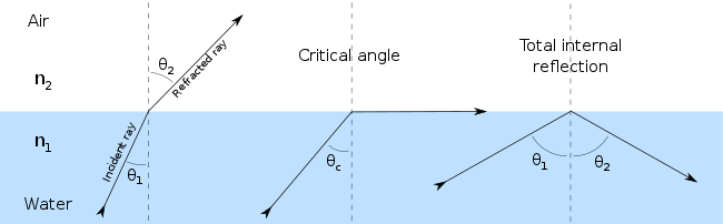
Truth be told, impression of light may happen at whatever point light goes from a medium of a given refractive record into a medium with an alternate refractive list. In the most broad case, a specific part of the light is reflected from the interface, and the rest of refracted. Settling Maxwell's conditions for a light beam striking a limit permits the inference of the Fresnel conditions, which can be utilized to anticipate the amount of the light is reflected, and what amount is refracted in a given circumstance. This is closely resembling the way impedance jumble in an electric circuit causes impression of signs. Add up to interior impression of light from a denser medium happens if the edge of occurrence is more prominent than the basic point.
Add up to inside reflection is utilized as a methods for centering waves that can't successfully be reflected by normal means. X-beam telescopes are developed by making a merging "passage" for the waves. As the waves interface at low edge with the surface of this passage they are reflected toward the concentration point (or toward another connection with the passage surface, in the long run being coordinated to the locator at the core interest). A customary reflector would be futile as the X-beams would essentially go through the planned reflector.
If the reflecting surface is very smooth, the reflection of light that occurs is called specular or regular reflection. The laws of reflection are as follows:
- The incident ray, the reflected ray and the normal to the reflection surface at the point of the incidence lie in the same plane.
- The angle which the incident ray makes with the normal is equal to the angle which the reflected ray makes to the same normal.
- The reflected ray and the incident ray are on the opposite sides of the normal.
These three laws can all be derived from the Fresnel equations.
which is depicted by Maxwell's conditions. Light waves occurrence on a material initiate little motions of polarization in the individual iotas (or swaying of electrons, in metals), making every molecule transmit a little auxiliary wave every which way, similar to a dipole reception apparatus. Every one of these waves signify give specular reflection and refraction, as per the Huygens– Fresnel rule.
On account of dielectrics, for example, glass, the electric field of the light follows up on the electrons in the material, and the moving electrons produce fields and turn out to be new radiators. The refracted light in the glass is the mix of the forward radiation of the electrons and the episode light. The reflected light is the blend of the regressive radiation of the majority of the electrons.


#/media/File:Mount_Hood_reflected_in_Mirror_Lake,_Oregon.jpg)
#/media/File:Reflection_angles.svg)
#/media/File:RefractionReflextion.svg)
#/media/File:F%C3%A9nyvisszaver%C5%91d%C3%A9s.jpg)